- Introduction
- SMD Component Enclosures
- Sizes of SMD components
- SMD resistors
- SMD capacitors
- SMD coils and chokes
- SMD transistors
- Labeling SMD Components
- Soldering SMD Components
Introduction
Today, not only ordinary components with conclusions, but also such small, dark ones, on which it is not possible to understand what is written, are available to a modern radio amateur. They are called "SMD". In Russian, it means "components surface mount". Their main advantage is that they allow the industry to assemble boards using robots that quickly place SMD components in their places on printed circuit boards, then bake them in bulk and get mounted printed circuit boards at the output. Per person those operations remain that the robot cannot perform, while it cannot.
The use of chip components in amateur radio practice is also possible, even necessary, as it reduces the weight, size and cost of the finished product. Yes, and virtually no drilling.
For those who first encountered SMD components, confusion is natural. How to understand their diversity: where is the resistor, and where is the capacitor or transistor, what are their sizes, which cases of smd parts exist? You will find the answers to all these questions below. Read, come in handy!
Chip Component Enclosures
Quite conditionally, all the components of surface mounting can be divided into groups according to the number of conclusions and the size of the case:
| conclusions / size | Very very small | Very small | Small | Medium |
| 2 pins | SOD962 (DSN0603-2), WLCSP2 *, SOD882 (DFN1106-2), SOD882D (DFN1106D-2), SOD523, SOD1608 (DFN1608D-2) | SOD323, SOD328 | SOD123F, SOD123W | SOD128 |
| 3 pins | SOT883B (DFN1006B-3), SOT883, SOT663, SOT416 | SOT323, SOT1061 (DFN2020-3) | SOT23 | SOT89, DPAK (TO-252), D2PAK (TO-263), D3PAK (TO-268) |
| 4-5 conclusions | WLCSP4 *, SOT1194, WLCSP5 *, SOT665 | SOT353 | SOT143B, SOT753 | SOT223, POWER-SO8 |
| 6-8 conclusions | SOT1202, SOT891, SOT886, SOT666, WLCSP6 * | SOT363, SOT1220 (DFN2020MD-6), SOT1118 (DFN2020-6) | SOT457, SOT505 | SOT873-1 (DFN3333-8), SOT96 |
| \u003e 8 pins | WLCSP9 *, SOT1157 (DFN17-12-8), SOT983 (DFN1714U-8) | WLCSP16 *, SOT1178 (DFN2110-9), WLCSP24 * | SOT1176 (DFN2510A-10), SOT1158 (DFN2512-12), SOT1156 (DFN2521-12) | SOT552, SOT617 (DFN5050-32), SOT510 |
Of course, not all cases are indicated in the table, since the real industry produces components in new cases faster than standard bodies keep up with them.
Cases of SMD components can be with or without outputs. If there are no conclusions, then on the case there are contact pads or small solder balls (BGA). Also, depending on the manufacturer, the parts may vary in marking and dimensions. For example, capacitors may vary in height.

Most SMD component housings are designed for installation using special equipment that radio amateurs do not have and are unlikely to ever have. This is due to the technology of soldering such components. Of course, with some perseverance and fanaticism, you can solder at home.
Types of SMD Enclosures by Name
| Title | Decryption | number of conclusions |
| SOT | small outline transistor | 3 |
| SOD | small outline diode | 2 |
| SOIC | small outline integrated circuit | \u003e 4, in two lines on the sides |
| TSOP | thin outline package (thin SOIC) | \u003e 4, in two lines on the sides |
| SSOP | seated SOIC | \u003e 4, in two lines on the sides |
| Tssop | thin seated SOIC | \u003e 4, in two lines on the sides |
| QSOP | Quarter size SOIC | \u003e 4, in two lines on the sides |
| VSOP | Smaller QSOP | \u003e 4, in two lines on the sides |
| Plcc | ICs in a plastic case with pins bent under the case with a letter J | \u003e 4, in four lines on the sides |
| CLCC | ICs in a ceramic case with leads bent under the case with a letter J | \u003e 4, in four lines on the sides |
| QFP | square flat case | \u003e 4, in four lines on the sides |
| LQFP | low profile QFP | \u003e 4, in four lines on the sides |
| PQFP | plastic QFP | \u003e 4, in four lines on the sides |
| Cqfp | ceramic QFP | \u003e 4, in four lines on the sides |
| TQFP | thinner QFP | \u003e 4, in four lines on the sides |
| Pqfn | power QFP without pins with a radiator pad | \u003e 4, in four lines on the sides |
| Bga | Ball grid array. Array of balls instead of pins | pin array |
| Lfbga | low profile FBGA | pin array |
| Cga | case with input and output conclusions from refractory solder | pin array |
| CCGA | CGA in ceramic case | pin array |
| μBGA | micro bga | pin array |
| FCBGA | Flip-chip ball grid array. Massort of balls on a substrate to which a crystal with a heat sink is soldered | pin array |
| LLP | leadless housing |
Of all this zoo, chip components for amateur use can come in handy: chip resistors, chip capacitors, chip inductors, chip diodes and transistors, LEDs, zener diodes, some microcircuits in SOIC packages. Capacitors usually look like simple parallelepipeds or small barrels. Barrels are electrolytic, and parallelepipeds will most likely be tantalum or ceramic capacitors.

Sizes of SMD Components
Chip components of the same denomination can have different dimensions. The dimensions of the SMD component are determined by its "size". For example, chip resistors have sizes from "0201" to "2512". These four numbers encode the width and length of the chip resistor in inches. Below in the tables you can see the sizes in millimeters.
smd resistors

| Rectangular Chip Resistors & Ceramic Capacitors | |||||
| Size | L mm (in) | W mm (in) | H mm (in) | A mm | Tue |
| 0201 | 0.6 (0.02) | 0.3 (0.01) | 0.23 (0.01) | 0.13 | 1/20 |
| 0402 | 1.0 (0.04) | 0.5 (0.01) | 0.35 (0.014) | 0.25 | 1/16 |
| 0603 | 1.6 (0.06) | 0.8 (0.03) | 0.45 (0.018) | 0.3 | 1/10 |
| 0805 | 2.0 (0.08) | 1.2 (0.05) | 0.4 (0.018) | 0.4 | 1/8 |
| 1206 | 3.2 (0.12) | 1.6 (0.06) | 0.5 (0.022) | 0.5 | 1/4 |
| 1210 | 5.0 (0.12) | 2.5 (0.10) | 0.55 (0.022) | 0.5 | 1/2 |
| 1218 | 5.0 (0.12) | 2.5 (0.18) | 0.55 (0.022) | 0.5 | 1 |
| 2010 | 5.0 (0.20) | 2.5 (0.10) | 0.55 (0.024) | 0.5 | 3/4 |
| 2512 | 6.35 (0.25) | 3.2 (0.12) | 0.55 (0.024) | 0.5 | 1 |
| Barrel Chip Resistors & Diodes | |||||
| Size | Ø mm (in) | L mm (in) | Tue | ||
| 0102 | 1.1 (0.01) | 2.2 (0.02) | 1/4 | ||
| 0204 | 1.4 (0.02) | 3.6 (0.04) | 1/2 | ||
| 0207 | 2.2 (0.02) | 5.8 (0.07) | 1 | ||
smd capacitors
Ceramic chip capacitors coincide in size with chip resistors, but tantalum chip capacitors have their own system of sizes:

| Tantalum Capacitors | |||||
| Size | L mm (in) | W mm (in) | T mm (in) | B mm | A mm |
| A | 3.2 (0.126) | 1.6 (0.063) | 1.6 (0.063) | 1.2 | 0.8 |
| B | 3.5 (0.138) | 2.8 (0.110) | 1.9 (0.075) | 2.2 | 0.8 |
| C | 6.0 (0.236) | 3.2 (0.126) | 2.5 (0.098) | 2.2 | 1.3 |
| D | 7.3 (0.287) | 4.3 (0.170) | 2.8 (0.110) | 2.4 | 1.3 |
| E | 7.3 (0.287) | 4.3 (0.170) | 4.0 (0.158) | 2.4 | 1.2 |
smd inductors and chokes
Inductances are found in many types of enclosures, but enclosures obey the same law of standard sizes. This facilitates automatic installation. Yes, and we, ham radio, make it easier to navigate.
All kinds of coils, chokes and transformers are called "winding products." Usually we wind them ourselves, but sometimes you can buy finished products. Moreover, if SMD options are required, which are available with a lot of bonuses: magnetic shielding of the case, compactness, closed or open case, high quality factor, electromagnetic shielding, a wide range of operating temperatures.

It is better to select the required coil according to the catalogs and the required size. The standard sizes, as for chip resistors, are set using the code of four numbers (0805). In this case, “08” indicates the length, and “05” is the width in inches. The actual size of such an SMD component will be 0.08x0.05 inches.
smd diodes and zener diodes
Diodes can be both in cylindrical cases, and in cases in the form of small parallelepipeds. The cylindrical diode housings are most often represented by MiniMELF (SOD80 / DO213AA / LL34) or MELF (DO213AB / LL41) housings. Sizes for them are set as well as for coils, resistors, capacitors.

| Diodes, Zener Diodes, Capacitors, Resistors | |||||
| Type of shell | L * (mm) | D * (mm) | F * (mm) | S * (mm) | Note |
| DO-213AA (SOD80) | 3.5 | 1.65 | 048 | 0.03 | Jedec |
| DO-213AB (MELF) | 5.0 | 2.52 | 0.48 | 0.03 | Jedec |
| DO-213AC | 3.45 | 1.4 | 0.42 | - | Jedec |
| ERD03LL | 1.6 | 1.0 | 0.2 | 0.05 | Panasonic |
| ER021L | 2.0 | 1.25 | 0.3 | 0.07 | Panasonic |
| ERSM | 5.9 | 2.2 | 0.6 | 0.15 | PANASONIC, GOST R1-11 |
| MELF | 5.0 | 2.5 | 0.5 | 0.1 | CENTS |
| SOD80 (miniMELF) | 3.5 | 1.6 | 0.3 | 0.075 | PHILIPS |
| SOD80C | 3.6 | 1.52 | 0.3 | 0.075 | PHILIPS |
| SOD87 | 3.5 | 2.05 | 0.3 | 0.075 | PHILIPS |
smd transistors
SMD transistors can also be of small, medium, or high power. They also have matching enclosures. The transistor cases can be divided into two groups: SOT, DPAK.

I want to draw attention to the fact that in such cases there can also be assemblies of several components, and not just transistors. For example, diode assemblies.
Marking SMD Components
It sometimes seems to me that the labeling of modern electronic components has turned into a whole science, similar to history or archeology, since in order to figure out which component is installed on the board, sometimes you need to conduct a whole analysis of the elements surrounding it. In this regard, the Soviet output components, on which the face value and the model were written in text, were just a dream for an amateur, since there was no need to stir up piles of reference books to figure out what these details were.
The reason lies in the automation of the assembly process. SMD components are installed by robots in which sectional baboons are installed (similar to once baboons with magnetic tapes) in which chip components are located. The robot doesn’t care what is in the babin and whether the parts have markings. Marking is needed by man.
Soldering Chip Components
At home, chip components can only be soldered to a certain size, size 0805 is considered more or less comfortable for manual installation. Smaller components are already soldered using a stove. Moreover, for high-quality soldering at home, a whole range of measures should be observed.
Diode marking
Marking of output diodes:
The most common coding systems are:
- Jedec (USA) - Standardized EIA370 N-Series Numbering System.
Type of code: <цифра><буква><серийный номер>[suffix].
The first digit is a digit reflecting the number of transitions in an element (1 for diodes).
The letter is always the letter “N”.
Serial number is a two-, three- or four-digit number that reflects the serial number of registration of a semiconductor device in the EIA.
Suffix - reflects the breakdown of devices of the same type into various standard ratings by characteristic parameters. The suffix may consist of one or more letters.
For example: 1N34A / 1N270 (germanium diode), 1N914 / 1N4148 ( silicon diode), 1N4001-1N4007 (1A silicon rectifier diode) and 1N54xx (3A high-power silicon rectifier diode).
- PRO ELECTRON (Europe);
The designation consists of four elements.
The first element is a letter indicating the type of semiconductor material used in the device:
- A is germanium;
- B is silicon;
- C is gallium arsenide;
- R - other semiconductor materials.
The second element is a letter indicating the type of semiconductor device:
- A - low-power pulse and universal diodes;
- B - varicaps;
- E - tunnel diodes;
- G - special-purpose devices (for example, generator), as well as complex devices containing several different components in one housing;
- H - magnetically sensitive diodes;
- P - photosensitive devices (photodiodes, phototransistors, etc.);
- Q - light emitting devices (LEDs, IR diodes, etc.);
- X - multiplier diodes;
- Y - rectifier diodes, boosters;
The third element is the letter, which is set only for devices intended for use in special equipment (industrial, professional, military, etc.). The letters “Z”, “Y”, “X” or “W” are commonly used. In the designations of general-purpose devices, this element is missing.
The fourth element is the two-, three- or four-digit serial number of the device.
The designation may contain some additional elements. For example, the suffix is \u200b\u200bthe same as in the JEDEC system, which reflects the breakdown of devices of the same type into different standard ratings by characteristic parameters.
For some types of devices (such as zener diodes), an additional classification may be applied. At the same time, an additional code is added to the main designation (it can also be through a hyphen or fraction). For example, an additional code is often used containing information about the stabilization voltage and its possible spread (“A” - 1%, “B” - 2%, “C” - 5%, “D” - 10%, “E” - 15 %). If the stabilization voltage is not an integer, then the letter V is placed instead of a comma. In the additional code for rectifier diodes indicates the maximum amplitude of the reverse voltage.
For example, BZY88C4V7 is silicon zener diode special purpose with registration number 88, stabilization voltage 4.7 V with a maximum deviation of this voltage from the nominal value ± 5%.
Table 1 - Color coding of diodes (PRO ELECTRON).
- JIS (Japan, Asia);
The designation consists of five elements.
The first element is a digit reflecting the number of transitions in the element (0 - photodiodes; 1 - diodes).
The second element is the letter “S” for Semiconductors.
The third element is a letter indicating the type of semiconductor device:
- E - diodes;
- G - Gunn diodes;
- Q - light emitting diodes;
- R - rectifier diodes;
- S - low-current diodes;
- T - avalanche diodes;
- V - varicaps, p-i-n-diodes, diodes with charge accumulation;
- Z - zener diodes, limiters.
The fourth element is the serial (registration) number of the device.
The fifth element is the modification of the device (“A” is the first, “B” is the second, etc.).
After standard marking, an additional index (“N”, “M”, “S”) may follow, reflecting some of the special properties of the device.
 Table 2 - Color coding of diodes (JIS-C-7012 and JEDEC).
 Marking SMD Diodes:
SMD diodes are usually labeled with an alphanumeric code. Depending on the type of case (i.e. its size) and the manufacturer, one or another coding system is used. It is quite obvious that it is not possible to consider all types of coding. Therefore, some codes for the most commonly used diode housings will be discussed below. You can see a more complete version of the coding systems of SMD diodes.
For SOD80 (MiniMELF) enclosures:
 Table 3 - Coding of SMD diodes in the SOD80 package.
 Example: BZV87-1V4 - silicon zener diode for stabilization voltage 1.4 V.
The remaining values \u200b\u200bof the zener diodes are encoded in a similar way.
Color coding:
 Table 4 - Color coding of SMD diodes in the SOD80 package.
 Often, the manufacturer encodes only the type of diode:
 Table 5 - Color coding of the type of SMD diodes.
 For enclosuresSOT89:
 Table 6 - Coding of SMD diodes in the SOT89 package.
 For housings SOD123, SOD323:
The symbol of the diodes in the diagrams
 Figure 7 - Designation of the findings of the diode.
  Figure 8 - UGO diodes.
 Near symbol indicates the type of element (VD) and serial number.
SMD Component Enclosures
|
Despite the large number of standards governing the requirements for electronic components enclosures, many companies produce elements in enclosures that do not meet international standards. There are also situations where the case, which has standard sizes, has a non-standard name. |


|
* Depending on the technologies the company possesses, the standardized variations with respect to the basic dimensions also vary. The most common tolerances: ± 0.05 mm - for the case up to 1 mm long, for example 0402; ± 0.1 mm - up to 2 mm, for example SOD-323; ± 0.2 mm - up to 5 mm; ± 0.5 mm - over 5 mm. Slight discrepancies in sizes between different companies are due to varying degrees of accuracy in the conversion of inches to mm, as well as indicating only min, max or nominal size. ** Cases with the same name may have different heights. This is due to: for capacitors - the value of capacitance and operating voltage, for resistors - dissipated power, etc. Continuous numbering of the most popular SMD cases. |


** There is a tendency when, next to the internal designation of the building, the name of this building is indicated according to one of the standards - JEDEC or EIAJ.
*** Different companies under the same name may have cases with different sizes; no cases are indicated that are outwardly similar to those presented, but have overall dimensions that differ from standard ones, for example, SOD15 from SGS-Thomson.
Resistors
Code marking firms PHILIPS.
Philips encodes resistors in accordance with generally accepted standards, i.e. the first two or three digits indicate the denomination in ohms, and the last indicate the number of zeros (multiplier). Depending on the accuracy of the resistor, the value is encoded in the form of 3 or 4 characters. Differences from the standard encoding may consist in the interpretation of the digits 7, 8 and 9 in the last character.
The letter R acts as a decimal point or, if it is at the end, indicates a range. A single “0” indicates a resistor with zero resistance (Zero - Ohm).

|
Resistors |
Marking with 3 digits.
The first two digits indicate the values \u200b\u200bin ohms, the last - the number of zeros. It applies to resistors from the E-24 series, tolerances of 1 and 5%, sizes 0603, 0805 and 1206.
![]()
Marking with 4 digits.
The first three digits indicate the values \u200b\u200bin ohms, the last - the number of zeros. It applies to resistors from the E96 series, with a tolerance of 1%, sizes 0805 and 1206. The letter R plays the role of a decimal point.


|
Many companies produce special jumper wires with normalized resistance and diameter (0.6 mm, 0.8 mm) and resistors with "zero" resistance as fusible inserts or jumpers. |
|
Marking SMD Resistors. |
SMD resistors of size 0402 are not marked, resistors of other sizes are marked in various ways, depending on the size and tolerance.
Resistors with a tolerance of 2%, 5% and 10% of all sizes are marked with three digits, the first two of which indicate the mantissa, and the last is an exponent on the basis of 10 to determine the resistor value in Ohms. If necessary, the letter R is added to the significant digits to indicate the decimal point. For example, 513 means that the resistor has a nominal value of 51x103 ohms \u003d 51 kΩ.
Resistors with a tolerance of 1% of sizes from 0805 and higher are marked with four digits, the first three of which indicate the mantissa, and the last is an exponent on the basis of 10 to specify the resistor value in Ohms. The letter R also stands for decimal point. For example, marking 7501 means that the resistor is rated at 750x101 Ohm \u003d 7.5 KΩ.
Resistors with a tolerance of 1% size 0603 are labeled using the EIA-96 table below with two numbers and one letter. The numbers specify the code by which the mantissa is determined from the table, and the letter is the exponent on the basis of 10 to determine the resistor value in Ohms. For example, a 10C mark means that the resistor is rated at 124x102 ohms \u003d 12.4 kΩ.

Marking Ceramic SMD Capacitors
Marks of SMD ceramic capacitors.

Capacitors are manufactured with different types of dielectrics: NP0, X7R, Z5U and Y5V .... NP0 (COG) dielectric has a low dielectric constant, but good temperature stability (TKE is close to zero). High-value SMD capacitors manufactured using this dielectric are the most expensive. X7R dielectric has higher dielectric constantbut less thermal stability. The dielectrics Z5U and Y5V have a very high dielectric constant, which allows the manufacture of capacitors with a large value of capacitance, but having a significant variation in parameters. XDR and Z5U dielectric SMD capacitors are used in general purpose circuits.
In general, high permeability dielectric ceramic capacitors are denoted by three symbols according to the EIA, the first two of which indicate the lower and upper limits of the operating temperature range, and the third - allowable change capacities in this range. The decoding of the code symbols is given in the table.

Capacitor Rating Table

Marking Electrolytic SMD Capacitors
The capacitance and operating voltage of SMD electrolytic capacitors are often indicated by their direct recording, for example 10 6V - 10uF 6V. Sometimes a code is used instead, which usually consists of a letter and 3 digits. The first letter indicates the operating voltage in accordance with the table on the left, and 3 digits (2 digits and a multiplier) give the capacitance in pF. The bar indicates the output of positive polarity.
For example, the A475 marking indicates a 4.7uF capacitor with an operating voltage of 10V. It is followed by a three-digit capacity rating code in pF, in which the last digit indicates the number of zeros in the rating. For example, the marking E105 denotes a capacitor with a capacity of 1,000,000pF \u003d 1.0uF with an operating voltage of 25V.
In amateur radio broad practical use received not only ordinary radio components with conclusions, but also very small radio elements with obscure inscriptions. They are called "SMD", that is, "surface mount radio parts". In the labeling of SMD components, this reference material should help to understand.
all SMD components can be divided into several groups according to the size of the case and the number of conclusions:
| conclusions / size | Very very small | Very small | Small | Medium |
| 2 pins | SOD962 (DSN0603-2), WLCSP2 *, SOD882 (DFN1106-2), SOD882D (DFN1106D-2), SOD523, SOD1608 (DFN1608D-2) | SOD323, SOD328 | SOD123F, SOD123W | SOD128 |
| 3 pins | SOT883B (DFN1006B-3), SOT883, SOT663, SOT416 | SOT323, SOT1061 (DFN2020-3) | SOT23 | SOT89, DPAK (TO-252), D2PAK (TO-263), D3PAK (TO-268) |
| 4-5 conclusions | WLCSP4 *, SOT1194, WLCSP5 *, SOT665 | SOT353 | SOT143B, SOT753 | SOT223, POWER-SO8 |
| 6-8 conclusions | SOT1202, SOT891, SOT886, SOT666, WLCSP6 * | SOT363, SOT1220 (DFN2020MD-6), SOT1118 (DFN2020-6) | SOT457, SOT505 | SOT873-1 (DFN3333-8), SOT96 |
| \u003e 8 pins | WLCSP9 *, SOT1157 (DFN17-12-8), SOT983 (DFN1714U-8) | WLCSP16 *, SOT1178 (DFN2110-9), WLCSP24 * | SOT1176 (DFN2510A-10), SOT1158 (DFN2512-12), SOT1156 (DFN2521-12) | SOT552, SOT617 (DFN5050-32), SOT510 |
Cases of SMD elements can be with and without conclusions. If there are no leads, then there are pads or very small solder balls (BGA) on the case. In addition, all SMDs differ in size and marking. For example, containers may have different heights.

Basically, SMD component housings are mounted using special equipment, which not every radio amateur has. But with a great desire, you can solder BGA components in houses.
SMD Enclosure Components for SMD

Despite the huge number of standards governing the requirements for chip housings, many manufacturers produce elements in housings that do not meet international standards. There are situations when a case with standard sizes has a non-standard name.
Usually the name of the case is from four digits, which indicate its length and width. But for some firms, these parameters are set in inches, while for others - in millimeters. For example, the name 0805 is obtained as follows: 0805 \u003d length x width \u003d (0.08 x 0.05) inchesand the case is 5845 (5.8 x 4.5) mm: Cases with the same name are of different heights (This is due to: for capacitors - the value of capacitance and operating voltage, for resistors - dissipated power, etc.), various contact pads are made from various materials, but designed for a standard installation location. The table below shows the dimensions in millimeters of the most popular types of cases.


Types SMD Enclosures by foreign names:

Of all this abundance of chip elements for a radio amateur, the following can be used: chip resistors, inductances, capacitors, diodes and transistors, LEDs, zener diodes, some microcircuits in SOIC design. Capacities usually resemble simple parallelepipeds or small barrels. Barrels are electrolytic capacitors, and parallelepipeds are tantalum or ceramic.

Marking SMD Components Resistors |
All chip surface mount resistors are usually labeled. In addition to resistances in the 0402th case, because they do not have markings due to their miniature size. Resistors of other sizes are marked with two main methods. If the chip of resistors has a tolerance of resistance of 2%, 5% or 10%, then their marking consists of 3 digits: the first two are the mantissa, and the third is the degree for the decimal base, i.e., the resistance value in Ohms is obtained. For example, the resistance code 106 - the first two digits 10 - is the mantissa, 6 - the degree, in the end we get 10x10 6, that is 10 Mom. Sometimes the Latin letter R is added to the digital marking - it is an additional factor and indicates a decimal point. SMD resistors of size 0805 and more, have an accuracy of 1% and are indicated by a four-digit code: the first three are the mantissa, and the last is the degree for the decimal base. The Latin symbol R can also be added to this marking. For example, the resistance code 3303 - 330 is the mantissa, 3 is the degree, as a result we get 330x10 3, i.e. 33 kOhm. Code sMD marking resistances with a tolerance of 1% and size 0603 is indicated by just two numbers and a letter using the table. The numbers indicate the code by which the mantissa value is selected from it, and the letter is a factor with a decimal base. For example, code 14R — the first two digits 14 — is the code. According to the table for code 14, the mantissa value is 137, R is a degree equal to 10 -1, as a result we get 137x10 -1, that is 13.7 Ohms. Resistors with zero resistance (jumpers) are simply marked with the number 0.
Each semiconductor device -smd transistor, has its own unique designation or marking, according to which it can be identified from a bunch of other chip components.
Marking SMD Diodes |
 Car generator and how to check it
 Safe use of household electrical appliances
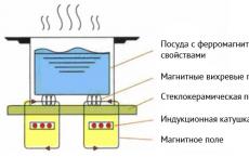 Economical Electric Cookers