Greetings!
Car generator and how to check it.
I want to spend a little of your time reading an article about a car generator and checking it.
If the battery charge system has stopped working, then it is not necessary to immediately sin on the generator. And suddenly, the wire between the generator and the battery just fell off. It is better to check the generator before removing it from the vehicle. It is necessary to measure the voltage at the generator contacts with a voltmeter with the engine running. If with the engine running on the generator contacts going to the battery, the voltage is not higher than the battery voltage (not more than 13 V), then definitely need to remove the generator.
Operational Amplifiers Analog circuits continuously process a signal over time. Currently, the most used component is an operational amplifier. Voltage and current sensors Research time: 15 minutes Purpose After reading this section, you will be able to describe the principle of the main voltage and current sensors for an individual assessment of the task.
First, the elements of the inter-frequency frequency are calculated. Joiner Michal. 5 Laboratory work No. 4 No. of the task. Working rectifiers time to study: 15 minutes Objectives After reading this paragraph, you will be able to describe the main operations of the operational involvement of independent directors to measure this task of the operational interpretation.
Important notice! You can not disconnect the battery from the on-board network of a running car in order to check the generator’s performance.
Such a warning can often be heard. But few can justify this. Like, they say that you can’t do that! And many shout the catch phrase of Dimon from "Our Rashi": "Don’t stop you, I did it a hundred times!"
Transmission technology 1 Transmission technology Key concepts and devices Transmission technology is the area of \u200b\u200bcommunication technology that designs, builds and operates transportation equipment. What effect does a dynamic filter have on different time constants?
A characteristic feature of these amplifiers. Features of linear operating networks and networks with non-linear feedback. How it works. An operational amplifier is a component that was originally developed. The measurement saw a sinusoid with a digital oscilloscope. Tasks: Measure with a digital oscilloscope the sawtooth wave signal and the log record - the time t that it takes in descending order.
So why, after all, knowledgeable people do not recommend disconnecting the battery when the engine is running? The car generator generates a three-phase EMF:
which straightens
. I will not go deep into theory. You can read about diode bridge
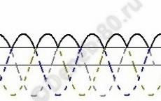
(Full Wave Rectifier). In general, a pulsating voltage is obtained at the output of the diode bridge (solid line in the figure): 
Regulators and controller functions As already mentioned, the properties of regulators determine the quality of control. When choosing a controller, it is necessary to take into account the transmission properties of the regulated system. Theory of electronic circuits Laboratory task No. 1 Measuring instructions Feedback and compensation Measure the frequency response of the inverting amplifier module in connection with the operational amplifier.
It used to be used in telecommunications to reuse transmission. In particular, this means voltage on both alternating and frequency. The main unit of converters 1 Fig. Detects the presence of water in the area where it is located. This, therefore, is the prevention of losses and insured events caused by defects in domestic water supply systems and companies. It is installed on the floor next to washing machines, dishwashers, boilers and in places where there is the possibility of an accident on the water supply.
The battery in this case acts as a capacitor (Smoothing Capacitor) of large capacity, which smooths out voltage ripples: 
On board the car a bunch of different sensors, ECU (ECU), sophisticated audio systems, amplifiers. All of them receive normal smoothed nutrition and are satisfied with it. And then suddenly a capacitor (battery) is disconnected, and all the electronics begin to receive some strange pulsating power supply with all sorts of emissions and transients. Someone will rest but be patient, but someone (for example, an ECU or an audio system) will say: “Well, there is such power in FIG!” and will bend. This is one of the options. Rectifier Diodes may not withstand surges and transients.
It has overload protection for a long service life and modified air cooling for better cooling and longer service life. Very smooth operation thanks to a separate engine and gearbox. Gearbox cover. Slim design with ergonomic rubber finish. The additional handle can be mounted flexibly in three positions.
Don’t miss the November issue next week. These are devices designed for installation in stationary substations. It is used to switch electrical circuit without load. They either work manually or with a cranked emergency control unit.
And if the voltage regulator takes the reference voltage from the battery? The battery is turned off and no one controls the output voltage from the generator! Most likely, everything that sits on board will burn. In general, a lottery. It can somehow ride, but once again something burns out.
Generator verification can be divided into several stages.
1. The first step is to check the voltage regulator (I will discuss the operation of the regulator below).
For verification, a current source with an adjustable output voltage is required. The positive output of the source is connected to the terminal, usually indicated B + (a thick wire from the plus of the battery goes to this terminal), and the same output must be connected to the terminal (indicated D +), to which the cathodes of 3 additional diodes are connected (Three Additional Diodes, Diode trio). The excitation winding and voltage regulator are fed from these 3 diodes. If additional diodes are absent (in some models of generators), then the field winding and the regulator are powered by the main diodes (then contact D + is absent). The negative terminal of the regulator is connected to the generator housing. If it is difficult to immediately determine the negative output, then you can ring the tester with the findings of the regulator with the generator housing. The output voltage of the regulator is removed from the brushes. A 12 V 5-10 W lamp or a voltmeter can be connected to the brushes' conclusions. But the lamp is more convenient in that it is easier to control. We set the output voltage to 12 V at the current source. Connect according to the figure:
The disconnector status is signaled on the front panel and at the same time electrically by auxiliary contacts. This is the balance of the international engineering fair, which took place at the Brno Exhibition Center in October. It serves as a projection tool for the design of switchboards, including warming control, front view, one- and three-pole circuit, a collection of components used. Similarly, we will submit an application for government, ticket sales, or various entertainment attractions.

We supply power to the regulator. When the voltage at the input of the regulator is 12 V, the output must have the same voltage. The lamp connected to the contacts of the brushes should be lit. We begin to gradually increase the voltage at the input of the regulator. The lamp naturally begins to glow brighter. Upon reaching a certain input voltage (usually 15-16 V), the lamp should go out. This means that the regulator is working properly. The lamp glow at an input voltage greater than 16 V, or the absence of its glow at all at an input voltage of 12 V, indicates a faulty voltage regulator. Or for errors in the connection diagram.
If you do not have an adjustable current source at hand, you can connect several batteries connected in series. For example, a battery with a voltage of 12 V and 3-4 batteries in series with it (for example, size AAA). From one battery, the lamp on the brushes should glow, and when adding batteries, go out. For the convenience of such a check, a switch of type DPDT. ().

Controller check video:
2. Checking rectifier bridge diodes.
It will require a multimeter. Before checking, you need to disconnect the diodes from the terminals of the windings, otherwise it will not be visible if there is an open in some diode.
The multimeter sets the diode test mode. Alternately, the circuit rings from the output of each diode, first to the positive contact B +, then onto the generator housing. The multimeter should show about 0.4-0.7 V with direct connection (the positive probe of the device to the output of the winding, the negative to the contact B +) It is also necessary to check the field diode power diodes. If they were sentenced to replacement, then you need to find diodes that are suitable for the parameters. The excitation winding of the Delta Autotechnik generator consumes about 6 A, so you need to choose diodes for a current of more than 2 A each, because diodes 3. For example, diodes are installed on the native rectifier Delta Autotechnik 1N5408. But these diodes are no longer recommended for use in new projects.
If in some case the readings are about 0 V, then the diode is shorted (broken), the lack of voltage in the direct and reverse connection to the diode also indicates a faulty diode (open).
The breakdown of one or more diodes does not condemn the entire rectifier bridge (although it is easier to replace it entirely). And on the generators of domestic cars usually plates with diodes are mounted with rivets, here we can say that "the game is not worth the candle." Those who decided to restore their own diode bridge -
3. Checking the rotor (field winding).
The multimeter sets the resistance measurement mode. The resistance of the winding on the contact rings of the rotor is measured. A healthy winding should have a resistance of 2-5 ohms (depending on the generator). If the device showed infinitely large resistance, it means a break in the winding. If the resistance is less than required, then most likely interturn circuit. Next, you can check the winding for leakage.
Attention! The test is carried out with a life-threatening voltage of 220 V, be careful!
From a 220 V network, in series through a 40 W incandescent lamp, voltage is supplied to the slip ring, and a second wire to the rotor housing. If the lamp starts to glow, then there is a leak in the winding. This winding must be replaced.

4. Checking the stator winding.
It is performed similarly. It is necessary to disconnect the terminals of the rectifier bridge diodes from the terminals of the windings. The stator windings have a very low resistance (about 0.2-0.3 Ohms), so you can not measure it with a conventional multimeter. Millimeter required. Or you can just make sure there is no break in the windings (the multimeter will show zero resistance). The leak test is carried out similarly to the rotor test. One wire is connected to the output of the stator winding, the other through an incandescent lamp to the housing. If everything is in order, the lamp does not light.
5. Checking the generator itself.
the voltage regulator is working, the diode bridge is working (or restored). All connections restored. It remains to check everything together. The generator is connected to a current source or battery as follows:

To check the generator, I recommend fixing it in a vice. The battery minus to the generator housing, and plus 12 V are supplied to the contact, designated as B +.A diode bridge and a voltage regulator are installed on the generator. We wind the cord onto the generator pulley so that when pulling the free end of the cord, the pulley rotates clockwise (if you look at the pulley in front). Close the key SA1, the lamp connected in series with the contact L, when power is supplied to the generator should be lit. When the current begins to pass through the lamp along the field winding and the winding creates a magnetic field, this can be felt by rotating the pulley. Now it will spin harder. Then you need to forcefully pull the free end of the cord. If everything is OK, if there are no errors in the connection, and if enough current flows through the field winding, the lamp will go out for a short time and light up again.
One more thing. Do not check the generator with a drill, etc. Even 1000-1300 rpm is a small amount for the rotation of the generator rotor. At this frequency, the generator will not be able to generate the necessary voltage, and the lamp will not go out.
A few words about the charge indicator lamp. This lamp is installed on the dashboard and serves as an indicator of the health of the generator. In some cases, a resistor is mounted on the parallel lamp so that the generator can operate when the lamp burns out. This lamp also limits the current passing through the field winding, which is very useful when the alternator belt breaks when a large current begins to flow through the winding.
The excitation winding of the generator is fed through this lamp when the ignition is turned on and the engine has not yet been started. When the ignition is turned on, the current passes from the positive terminal of the battery through the lamp, through the field winding and through the key element of the voltage regulator (transistor) and closes to a common wire. As soon as the generator begins to generate current, a positive voltage occurs at the second contact of the lamp after rectification with three additional diodes and the lamp goes out. If the power of this lamp is small, then a weak current will flow through the lamp, and accordingly through the field winding, which may not be enough to create magnetic field necessary size. Then, when the rotor rotates, the generator output will have a very small voltage. The charge indicator lamp will light. Of course, the voltage will be greater if you increase the rotor speed, but if the generator is not checked at the stand, then you can forget about it. On a particular car, the lamp power is selected so that, at the initial start of the engine, the generator generates a voltage sufficient to extinguish the lamp (i.e., this voltage should be equal to or greater than the voltage on the battery), and to energize at idle field winding. That is, that the generator feeds itself, and does not waste battery energy. In general, with a small lamp power, the rotation of the rotor will not affect its glow. A 5W lamp is sufficient to test some generators. In my case, with a Delta Autotechnik generator, a 5 W lamp was not enough. I had to connect 3 lamps of 5 W each in parallel.
A generator is a miniature automobile power station that converts the energy of rotation of the crankshaft of an internal combustion engine into electric current.
Generator History
The inventor of the automobile generator in the form in which it is installed today is the German engineer Robert Bosch. In 1887 he developed a low-voltage magneto for stationary engines, and by 1902 - magneto high voltage, which became the prototype of the "light machine" shown to him in 1906, that is, the first automobile DC generator.The prototype of the generator based on the "rotating triangle" was developed by the English physicist Michael Faraday in the mid-19th century
Car generator provides power to all volatile devices of the car and charges the battery with the engine running. The generator acts as a starter. In the case of a modern generator, in addition to the unit needed directly to generate electricity, other elements are also installed. It is a rectifier unit and voltage regulator. 
The device and principle of operation of the generator
The generator is similar in design to that fully illustrates the principle of reversibility of any electric machine. Inside the generator housing is a stator, recruited from steel elements with a three-phase winding of copper wire (coils). A rotor is located in the stator ring - a system of two magnets of different poles fixed to the shaft and an excitation winding. When the rotor rotates opposite the stator coils, the “north” and “south” rotor poles alternately pass. Thus, the direction of the magnetic flux penetrating the coil changes, which causes the appearance in it ac voltage. The rotation of the rotor of the generator, as a rule, is provided by a belt drive from. Also, a fan is usually mounted on the shaft, which provides cooling of the generator. Since the vehicle’s on-board network is designed for constant voltage, car generators are equipped with a conversion device alternating current in permanent. This rectifier is often called a diode bridge.
 If the generator fails where it is not possible to take the car to service, you can remove it yourself. In most cases, you don’t even have to climb under the car for this
Also, automotive generators have a built-in voltage regulator. Its function is to provide constant parameters of the on-board network, since the voltage generated by the generator directly depends on the rotor speed. A brush assembly with sliding contacts (“generator brushes”) adjacent to the ring contacts on the rotor shaft is also involved in the control system. The generator is driven by a drive belt mounted on a pulley coaxial with a pulley fixed to the front end.
Generator voltage
Voltage level electric currentgenerated by the generator is slightly higher than necessary for a twelve-volt on-board network, and ranges from 13.5 to 14.5 volts. It is necessary to car batterywhich, during the movement and operation of consumers, is never physically disconnected. If the generator, the battery would be constantly discharged, as it would seek to give current to the on-board network together with the generator.There is a direct correlation between generator power and battery capacity. If you put a battery too powerful in the car, it will never be fully charged
This is above the battery voltage level, which causes a small equalizing current to charge the battery. When the current that is supplied to the battery from the generator has a slightly higher voltage, the battery begins to take current, that is, charge.
Common generator malfunctions
The most common symptom of a generator malfunction is an insufficient battery charge. When diagnosing, first of all, it is necessary to check the belt tension. The correctness of this adjustment is of great importance - with insufficient tension, the belt slips, and the generator does not give the necessary voltage, with excessive tension, the shaft bearings wear out quickly and the rotor begins to run out. If the belt is in order, it is necessary to check the contacts of the chain and the brush assembly, since the brushes wear out during long-term operation. Abnormal operation of the voltage regulator and, as a consequence, increased voltage in the network, leads to a decrease in battery life and can cause burnout of the onboard circuit elements. Also, the most common malfunctions of automobile generators include burnout of the diode bridge, open circuit of the stator winding wires and short circuit windings on the case. The latter most often occurs due to moisture getting into parts of windings with damaged paintwork. It should be understood that, a neighbor’s car with a dead battery, you are at great risk of ruining the generator of your car. The problem is that the starter of the car you are trying to start consumes much more current at peak times than your generator can give out and process the voltage regulator. The average generator generates a current of 50 - 55 Amperes, and the starter of the car that you "light up" is able to consume up to 500 Amperes.The average cost of diagnostics and bulkheads of a foreign car generator is 5-6 thousand rubles. This is explained by the fact that they often use the same components
There are still ways to “light” another car safely. First of all, you can charge the battery in your neighbor’s car like your second. By attaching forceps, you immediately begin to do this. If you still want to start someone else’s car promptly, you must at least disconnect your battery during start-up or, conversely, start a second car from it, and turn off your engine for this time to save the generator.
 Car generator and how to check it
 Safe use of household electrical appliances
 Economical Electric Cookers