Component Cases for surface mount (SMD).
Despite the large number of standards governing the requirements for electronic components enclosures, many companies produce elements in enclosures that do not meet international standards. There are also situations where the case, which has standard sizes, has a non-standard name.
Often the name of the case consists of four numbers that display its length and width. But in some standards, these parameters are set in inches, and in others - in millimeters. For example, the name of the case 0805 is obtained as follows: 0805 \u003d length x width \u003d (0.08 x 0.05) inches, and the case 5845 has dimensions (5.8 x 4.5) mm: Cases with the same name can have different heights, different contact pads and made of various materials, but designed for installation on a standard installation location. Below are the dimensions in millimeters of the most popular types of cases.
* Depending on the technologies the company possesses, the standardized variations with respect to the basic dimensions also vary. The most common tolerances: ± 0.05 mm - for the case up to 1 mm long, for example 0402; ± 0.1 mm - up to 2 mm, for example SOD-323; ± 0.2 mm - up to 5 mm; ± 0.5 mm - over 5 mm. Slight discrepancies in sizes between different companies are due to varying degrees of accuracy in the conversion of inches to mm, as well as indicating only min, max or nominal size.
** Cases with the same name may have different heights. This is due to: for capacitors - the value of capacitance and operating voltage, for resistors - dissipated power, etc.
Continuous numbering of the most popular SMD cases.
Resistors
Code marking firms PHILIPS.
Philips encodes resistors in accordance with generally accepted standards, i.e. the first two or three digits indicate the denomination in ohms, and the last indicate the number of zeros (multiplier). Depending on the accuracy of the resistor, the value is encoded in the form of 3 or 4 characters. Differences from the standard encoding may consist in the interpretation of the digits 7, 8 and 9 in the last character.
The letter R acts as a decimal point or, if it is at the end, indicates a range. A single “0” indicates a resistor with zero resistance (Zero - Ohm). 
Thus, if you see code 107 on the resistor, this is not 10 with seven zeros (100 MΩ), but only 0.1 Ohm.
Resistors
BOURNS code mark.
Marking with 3 digits.
The first two digits indicate the values \u200b\u200bin ohms, the last - the number of zeros. It applies to resistors from the E-24 series, tolerances of 1 and 5%, sizes 0603, 0805 and 1206. 
Marking with 4 digits.
The first three digits indicate the values \u200b\u200bin ohms, the last - the number of zeros. It applies to resistors from the E96 series, with a tolerance of 1%, sizes 0805 and 1206. The letter R plays the role of a decimal point. 
Marking with 3 characters.
The first two characters are numbers indicating the resistance value in ohms, taken from the table below, the last character is a letter indicating the value of the multiplier:
S \u003d 0.01;
R is 0.1;
A \u003d 1;
B \u003d 10;
C \u003d 100;
D \u003d 1000;
E \u003d 10000;
F \u003d 100000.
It applies to resistors from the E-96 series, with a tolerance of 1%, size 0603.
Jumpers and resistors with zero resistance.
Many companies produce special jumper wires with normalized resistance and diameter (0.6 mm, 0.8 mm) and resistors with “zero” resistance as fusible inserts or jumpers.
Resistors are made in a standard cylindrical case with flexible leads (Zero-Ohm) or in a standard case for surface mounting (Jumper Chip).
The real values \u200b\u200bof the resistance of such resistors lie in the range of units or tens of milliohms (~ 0.005 ... 0.05 Ohms). In cylindrical housings, marking is carried out with a black ring in the middle, in surface mount housings (0603, 0805, 1206 ...), marking is usually absent or the code "000" (possibly "0") is applied.
Marking SMD Resistors.
SMD resistors of size 0402 are not marked, resistors of other sizes are marked in various ways, depending on the size and tolerance.
Resistors with a tolerance of 2%, 5% and 10% of all sizes are marked with three digits, the first two of which indicate the mantissa, and the last is an exponent on the basis of 10 to determine the resistor value in Ohms. If necessary, the letter R is added to the significant digits to indicate the decimal point. For example, 513 means that the resistor has a nominal value of 51x103 ohms \u003d 51 kΩ.
Resistors with a tolerance of 1% of sizes from 0805 and higher are marked with four digits, the first three of which indicate the mantissa, and the last is an exponent on the basis of 10 to specify the resistor value in Ohms. The letter R also stands for decimal point. For example, marking 7501 means that the resistor is rated at 750x101 Ohm \u003d 7.5 KΩ.
Resistors with a tolerance of 1% size 0603 are labeled using the EIA-96 table below with two numbers and one letter. The numbers specify the code by which the mantissa is determined from the table, and the letter is the exponent on the basis of 10 to determine the resistor value in Ohms. For example, a 10C mark means that the resistor is rated at 124x102 ohms \u003d 12.4 kΩ. 
Marking Ceramic SMD Capacitors
Marks of SMD ceramic capacitors.
Capacitors are manufactured with different types of dielectrics: NP0, X7R, Z5U and Y5V .... The dielectric NP0 (COG) has a low dielectric constantbut good temperature stability (TKE is close to zero). High-value SMD capacitors manufactured using this dielectric are the most expensive. The X7R dielectric has a higher dielectric constant, but lower thermal stability. The dielectrics Z5U and Y5V have a very high dielectric constant, which allows the manufacture of capacitors with a large value of capacitance, but having a significant variation in parameters. XDR and Z5U dielectric SMD capacitors are used in general purpose circuits.
In general, high permeability dielectric ceramic capacitors are denoted by three symbols according to the EIA, the first two of which indicate the lower and upper limits of the operating temperature range, and the third the permissible change in capacitance in this range. The decoding of the code symbols is given in the table. 
Marking Electrolytic SMD Capacitors
The capacitance and operating voltage of SMD electrolytic capacitors are often indicated by their direct recording, for example 10 6V - 10uF 6V. Sometimes a code is used instead, which usually consists of a letter and 3 digits. The first letter indicates the operating voltage in accordance with the table on the left, and 3 digits (2 digits and a multiplier) give the capacitance in pF. The bar indicates the output of positive polarity.
For example, the A475 marking indicates a 4.7uF capacitor with an operating voltage of 10V.
Marking Tantalum SMD Capacitors.
The marking of tantalum capacitors sizes A and B consists of a letter code of the rated voltage in accordance with the following table:
It is followed by a three-digit capacity rating code in pF, in which the last digit indicates the number of zeros in the rating. For example, the marking E105 denotes a capacitor with a capacity of 1,000,000pF \u003d 1.0uF with an operating voltage of 25V.
SMD capacitors due to their small size are marked with symbols and numbers. Depending on the type of capacitor (tantalum, electrolytic, ceramic, etc.), marking is carried out in various ways.
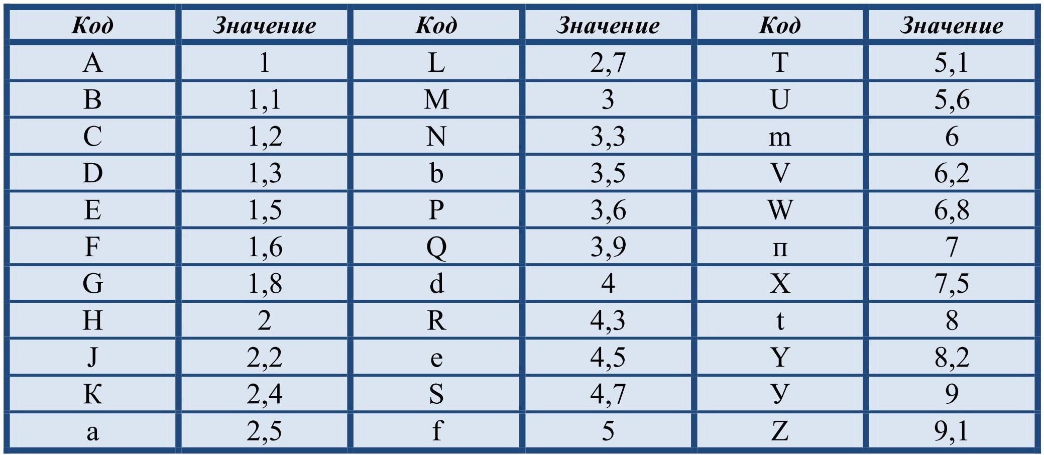
Marking Ceramic SMD Capacitors
The code of such capacitors consists of 2 or 3 characters and numbers. The first character (if any) indicates the manufacturer
(example K - Kemet), the second is the mantis, and the figure is an indicator of the degree of capacity in picoFarads.
Example
S3 This is a ceramic SMD capacitor with a capacitance of 4.7x10 3 pF
| Symbol | Mantis | Symbol | Mantis | Symbol | Mantis | Symbol | Mantis |
| A | 1.0 | J | 2.2 | S | 4.7 | a | 2.5 |
| B | 1.1 | K | 2.4 | T | 5.1 | b | 3.5 |
| C | 1.2 | L | 2.7 | U | 5.6 | d | 4.0 |
| D | 1.3 | M | 3.0 | V | 6.2 | e | 4.5 |
| E | 1.5 | N | 3.3 | W | 6.8 | f | 5.0 |
| F | 1.6 | P | 3.6 | X | 7.5 | m | 6.0 |
| G | 1.8 | Q | 3.9 | Y | 8.2 | n | 7.0 |
| H | 2.0 | R | 4.3 | Z | 9.1 | t | 8.0 |
encoders can have different types of dielectrics:
NP0 or C0G dielectric has low dielectric constant and good temperature stability. Z5U and Y5V dielectrics have a high dielectric constant with the help of which a large capacitance and a wider spread of parameters are achieved. X7R and Z5U are widely used in general purpose circuits.
Dielectrics are indicated by three characters, the first two are temperature limits and the third is the change in capacitance in% in this temperature range.
Z5U - accuracy +22, -56% in the temperature range from -55 o C to -125 o C to
| Temperature Range | Capacity change | ||||
| First character | lower limit | Second character | Upper limit | Third character | Accuracy |
| X | + 10 o C | 2 | +45 o C | A | 1.0% |
| Y | -30 o C | 4 | +65 o C | B | 1.5% |
| Z | -55 o C | 5 | +85 o C | C | 2.2% |
| 6 | +105 o C | D | 3.3% | ||
| 7 | +125 o C | E | 4.7% | ||
| 8 | +150 o C | F | 7.5% | ||
| 9 | +200 o C | P | 10% | ||
| R | 15% | ||||
| S | 22% | ||||
| T | +22%,-33% | ||||
| U | +22%,-56% | ||||
| V | +22%,-82% | ||||
Marking Electrolytic SMD Capacitors
For marking such capacitors, symbol-digital marking is also used in which the operating voltage is added. The decalcification consists of 1 character and 3 digits. Symbol means operating voltage
A475 A is the operating voltage, 47-value, 5-mantis.
A475 \u003d 47x10 5 pF \u003d 4.7x10 6 pF \u003d 4.7 mF 10V.
- e-2.5V;
- G-4B;
- J-6.3V;
- A-10B;
- C-16B;
- D-20V;
- E-25V;
- V-35V;
- H-50V.
There is also another marking used by such well-known companies as Panasonic, Hitach and others. Encoding is carried out in 3 main ways of encoding.
First way:
Marking is carried out using 3 characters, the first is the operating voltage, the second is the capacity value, the third is the multiplier. If only two symbols are indicated, this means that the operating voltage is not indicated (3rd symbol).
| The code | Capacity | Voltage | The code | Capacity | Voltage |
| A6 | 1.0 | 16/35 | ES6 | 4,7 | 25 |
| A7 | 10 | 4 | Ew5 | 0,68 | 25 |
| AA7 | 10 | 10 | GA7 | 10 | 4 |
| AE7 | 15 | 10 | GE7 | 15 | 4 |
| Aj6 | 2,2 | 10 | Gj7 | 22 | 4 |
| Aj7 | 22 | 10 | GN7 | 33 | 4 |
| AN6 | 3,3 | 10 | GS6 | 4,7 | 4 |
| AN7 | 33 | 10 | GS7 | 47 | 4 |
| AS6 | 4,7 | 10 | Gw6 | 6,8 | 4 |
| AW6 | 6,8 | 10 | Gw7 | 68 | 4 |
| CA7 | 10 | 16 | J6 | 2,2 | 6.3/7/20 |
| CE7 | 15 | 16 | Je7 | 15 | 6.3/7 |
| Cj6 | 4,7 | 10 | Gw6 | 6,8 | 4 |
| CN6 | 3,3 | 16 | Jn6 | 3,3 | 6,3/7 |
| CS6 | 4,7 | 16 | Jn7 | 33 | 6,3/7 |
| Cw6 | 6,8 | 16 | Js6 | 4,7 | 6,3/7 |
| DA6 | 1,0 | 10 | Js7 | 47 | 6,3/7 |
| DA7 | 10 | 20 | Jw6 | 6,8 | 6,3/7 |
| DE6 | 1,5 | 20 | N5 | 0,33 | 35 |
| DJ6 | 2,2 | 20 | N6 | 3,3 | 4/16 |
| DN6 | 3,3 | 20 | S5 | 0,47 | 25/35 |
| DS6 | 4,7 | 20 | VA6 | 1,0 | 35 |
| DW6 | 6,8 | 20 | Ve6 | 1,5 | 35 |
| E6 | 1,5 | 10/25 | Vj6 | 2,2 | 35 |
| EA6 | 1,0 | 25 | Vn6 | 3,3 | 35 |
| Ee6 | 1,5 | 25 | VS5 | 0,47 | 35 |
| Ej6 | 2,2 | 25 | Vw5 | 0,68 | 35 |
| EN6 | 3,3 | 25 | W5 | 0,68 | 20/35 |
The second way:
Marking with four symbols (letters and numbers) that indicate the rated capacity and operating voltage. The first character (letter) means the operating voltage, followed by 2 characters (digits) indicate the capacitance in pF, and the last character (digit) is the number of zeros. This marking of capacitors has 2 options.
The radio amateur, who first encountered the appearance of an SMD capacitor, wonders how to figure out all these “squares” and “barrels”, if some markings are missing at all, and if there is one, then you won’t understand what it means. But you want to keep up with the times, which means that you still have to figure out how to determine the ownership of an element of the board, to distinguish one component from another. As it turned out, there are still differences, and the labeling, although not always and not on all capacitors, gives an idea of \u200b\u200bthe parameters. There are, of course, SMD components without identification marks, but about everything in order. First you need to understand what this element is and what its purpose is.
Such a component works as follows. Unlike charges are charged to each of the two plates located inside (their polarity varies), which tend to one another according to the laws of physics. But the charge cannot “penetrate” the opposite plate due to the fact that the dielectric spacer between them, and therefore, having not found a way out and not having the opportunity to “get away” from the nearby opposite pole, accumulates in the capacitor until its capacity is filled.
Types of Capacitors
Capacitors differ in type, there are only three of them:
- Ceramic, film and similar non-polar are not marked, but their characteristics are easily determined using a multimeter. The range of capacities is from 10 picofarads to 10 microfarads.
- Electrolytic - made in the form of an aluminum barrel, labeled, seemingly reminiscent of the usual input, but mounted on the surface.
- Tantalum - the case is rectangular, the sizes are different. Release color - black, yellow, orange. Marked with a special code.
Electrolytic components
On such SMD components, capacitance and operating voltage are usually marked. For example, it can be 156v, which will mean that its characteristics are 15 microfarads and a voltage of 6 V.
And it may turn out that the marking is completely different, for example, D20475. A similar code defines the capacitor as 4.7 uF 20 V. The following is a list letter designations together with their voltage equivalent:
- e - 2.5 V;
- G - 4 V;
- J - 6.3 V;
- A - 10 V;
- C - 16 V;
- D - 20 V;
- E - 25 V;
- V - 35 V;
- H - 50 V.
The strip, as well as the slice, indicates the position of the “+” input.
Ceramic components
Marking of ceramic SMD capacitors has a wider number of notations, although the code itself contains only 2-3 characters and a digit. The first symbol, if any, indicates the manufacturer, the second indicates the rated voltage of the capacitor, but the figure is the capacitive indicator in pcF.
For example, the simplest marking T4 will mean that the capacitance of this ceramic capacitor is 5.1 × 10 in the 4th degree pcF.
The designation table for the rated voltage is shown below.
Marking Tantalum SMD Capacitors
Such elements of size "a" and "b" are marked with an alphabetic code for the rated voltage. There are 8 such letters - G, J, A, C, D, E, V, T. Each letter corresponds to voltage, respectively - 4, 6.3, 10, 16, 20, 25, 35, 50. It is followed by a capacitive code in pcF, consisting of three digits, the last of which will denote the number of zeros. For example, E105 marks a capacitor of 1,000,000 pcF \u003d 10 μF, and its nominal value will be 25 V.
Sizes C, D, E are marked with a direct code, like the code for electrolytic capacitors.
The main difficulty is that at the moment, although there are generally accepted notation rules, some large and well-known companies are introducing their own notation and code system, which is fundamentally different from the generally accepted. This is done in order to use only original parts and SMD components when repairing the printed circuit boards they manufactured.
Designation in schemes
In general, when repairing and soldering modern printed SMD boards, it’s most convenient when you still have a circuit at hand, looking at which it is much easier to figure out what is installed, to find out the location of a particular part, because the SMD capacitor may be completely different in appearance the same transistor. The designations of these details in the circuits remained the same as they were before the chips entered the market, and therefore, the capacity and other necessary characteristics can also be easily found by a radio amateur who did not encounter SMD components.
 Car generator and how to check it
 Safe use of household electrical appliances
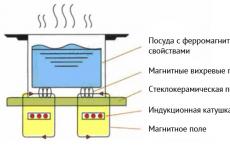 Economical Electric Cookers